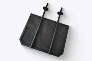

A coated titanium anode rarely fails because the coating was bad. It fails because the cell drifted outside the envelope the anode was selected for: current density crept up, fluoride entered the brine, the anode went cathodic during a shutdown, or scale was chipped off with a wire brush. This guide covers the precautions that prevent those failures, a maintenance schedule that fits a normal plant calendar, a cleaning procedure that removes scale without removing coating, and the fault-finding logic to apply when cell voltage starts to move. It applies to mixed metal oxide (MMO) and dimensionally stable anodes (DSA) used in chlor-alkali, sodium hypochlorite generation, electroplating, electrowinning, electrolytic copper foil, wastewater treatment and impressed current cathodic protection.
Four limits decide whether a coated titanium anode reaches its rated life: current density, temperature, electrolyte impurities (especially fluoride) and polarity. Keep all four inside specification, clean scale only with an approved dilute acid and a soft brush, and log cell voltage at constant current every shift. A slow voltage rise over months is normal coating wear; a step change is a fault.
100–3,000
A/m² typical current density
≤60 °C
usual aqueous rating
1–25 yr
service life at rated duty
±5 %
shift voltage vs baseline
Key facts at a glance
Parameter | Typical specification |
|---|---|
Substrate | Grade 1 or Grade 2 titanium strip per ASTM B265 |
Coating | Ru-Ir MMO for chlorine evolution, Ir-Ta MMO for oxygen evolution; typically 5–25 µm thick with 5–20 g/m² noble-metal loading |
Current density | 100–3,000 A/m² in most processes; 7,000–10,000 A/m² in electrolytic copper foil |
Temperature | Usually ≤60 °C in aqueous cells; confirm the rating for the specific coating |
Service life | 1–25 years at rated conditions, depending on duty |
First warning sign | Cell voltage rising at constant current |
Most common avoidable failures | Reverse polarity, fluoride ingress, operation above rated current density |
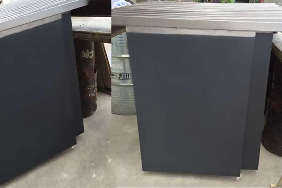
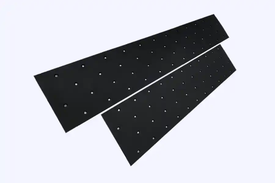
— Failure analysis
Why coated titanium anodes fail
A coated titanium anode fails in one of three ways: the electrocatalytic oxide is consumed, the titanium beneath it passivates, or the coating loses adhesion to the substrate. Five mechanisms account for almost every premature failure, and each leaves a different signature on cell voltage and on the anode surface. Reading that signature correctly is what separates a planned recoating from an unplanned shutdown.
Coating consumption
Noble-metal oxide dissolves and erodes from the active surface.
Typical cause: normal wear, accelerated by high current density and temperature.
Substrate passivation
A TiO₂ film grows under the coating and blocks current; brown, blue or gold interference colours may appear.
Typical cause: coating porosity, long shutdowns, low current density, fluoride.
Coating detachment
The oxide layer blisters or spalls away, leaving bare titanium patches.
Typical cause: weak surface pretreatment, thermal cycling, hydride formation.
Substrate corrosion
Titanium dissolves at pores, cut edges and welds, producing pitting, perforation and white TiO₂ deposits.
Typical cause: chloride or fluoride attack, coating defects, stray current.
Mechanical damage
Scratches, impact and abrasion through the coating to bare metal.
Typical cause: handling, installation, cleaning with abrasives.
Figure 1. Five mechanisms, five voltage signatures. The sparklines are schematic: the shape of the curve matters more than its scale, which depends on the cell.
Passivation and coating wear are routinely confused, and the mistake is expensive in both directions. Wear is gradual and predictable, so it can be planned around. Passivation can appear within days of an upset. If voltage rises steeply after a shutdown, a contamination event or a rectifier fault, suspect passivation or hydride formation rather than normal wear, and inspect before returning the cell to full load.
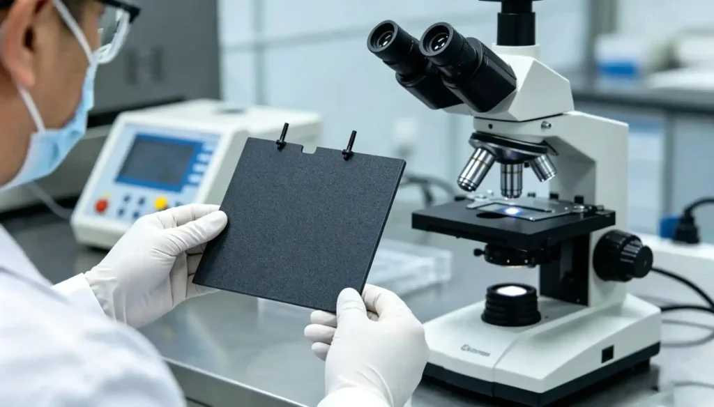
— Operating envelope
Ten operating precautions that decide service life
Almost every premature failure traces back to one of ten operating decisions. None of them requires new equipment; all of them require the cell to stay inside the envelope the anode was selected for.
1. Match the coating to the reaction, not to the catalogue
Ruthenium-iridium coatings are built for chlorine evolution;
iridium-tantalum coatings are built for oxygen evolution in acid. The difference is not marginal: in accelerated life tests in aqueous service, Ir-Ta coatings have been reported to last roughly 40 times longer than Ru-Ir coatings.
That does not make Ir-Ta the better anode — in chlorine service, ruthenium’s low chlorine overpotential is the entire reason the coating exists. A mismatched coating fails early no matter how carefully the cell is run.
2. Stay at or below rated current density
Coating life falls roughly in inverse proportion to current density; as a rule of thumb, halving the current density can extend life by three to five times. The limit applies locally as well as on average. A poor busbar joint, a partly immersed plate or a bent cathode can push one area of the anode far above nameplate while the cell ammeter still looks normal.
3. Never reverse polarity unless the cell was designed for it
Driving an MMO anode cathodic generates hydrogen and forms titanium hydride, which embrittles the substrate and lifts the coating. Some
sodium hypochlorite generators reverse polarity on a timer to shed cathode scale; that is safe only with anodes specified for reversal and a control sequence that caps cathodic time. A miswired rectifier can destroy a set of anodes in hours.
4. Treat fluoride as a hard limit
Fluoride complexes titanium and prevents the passive film from re-forming, so the substrate dissolves under the coating. Low single-digit mg/L concentrations are enough to shorten life measurably.
Check the fluoride content of the process water and the brine, not just the chemical specification sheet.
5. Hold temperature inside the coating rating
Most aqueous cells are rated to about 60 °C. Above the rating, oxide growth and coating dissolution both accelerate, and the effect compounds with current density. If cooling is lost, derate the current until it is restored rather than running hot for a shift.
6. Control pH and the rest of the electrolyte
Hardness scales the cathode and masks the anode, the chloride-to-sulphate ratio shifts which reaction dominates, and organics foul the active surface. Analyse the electrolyte weekly, not annually, and treat the analysis as a maintenance task rather than a laboratory formality.
7. Do not leave the anode at open circuit in concentrated brine
Stagnant, chlorine-rich electrolyte in crevices and under deposits is where passivation and crevice corrosion begin. Flush the cell and either keep it circulating or take the anode out and rinse it.
8. Keep the gap and the alignment
Anode-to-cathode distance sets cell voltage and current distribution. A sagging, warped or misaligned electrode creates a low-resistance path: current concentrates, the coating burns there first, and a sound anode is condemned for a local failure.
9. Handle the coating as a ceramic, because that is what it is
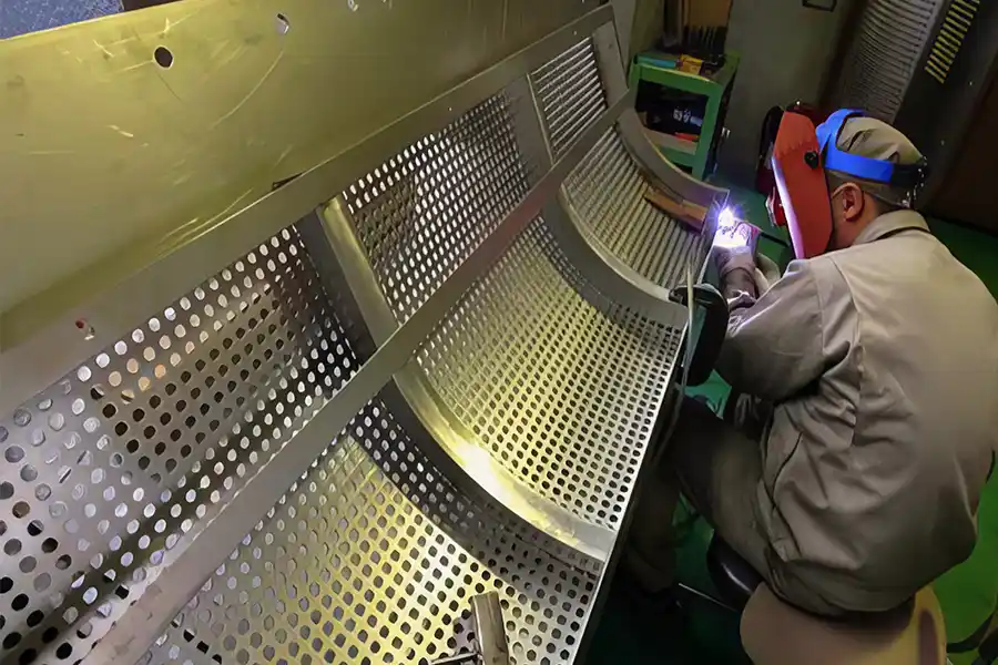
Clean gloves, no metal-to-coating contact, no stacking plates face to face, no standing on anodes, no lifting by the coated surface. A scratch through the coating to bare titanium becomes a corrosion site on the first day of service.
10. Maintain the electrical connection
Clean contact faces, correct torque, flat washers, and an infrared check of every joint at each scheduled stop. Contact resistance shows up first as heat, then as voltage, then as a failed anode.
Commissioning
Installation and first start-up
Correct installation takes an hour and protects years of service life. The sequence below is written for a plate or mesh anode in a divided or undivided cell; tube, rod and ribbon anodes follow the same logic.
Inspect before signing
Check coating colour uniformity, edge condition, weld quality and dimensions against the drawing, and photograph anything questionable. Transit damage is a supplier issue only if it is documented on arrival.
Verify the paperwork
Coating type and loading in g/m², substrate grade, dimensional report, and the accelerated life test data for the batch.
Protect the anode while it waits
Keep it in the original packaging on a clean, dry surface, away from oils, solvents and grinding dust.
Clean the contact surfaces, not the coating
Busbar faces are degreased and brushed; the coated working face is wiped with a soft cloth, and only with clean water if genuinely necessary.
Set the gap to drawing
Use the specified spacers and insulators, and confirm that no anode touches the cathode, the tank wall or the riser once the cell is filled.
Torque the connections to specification and record the values
Re-check them after the first thermal cycle.
Confirm polarity before energising
Trace the rectifier output to the anode busbar and mark it. Polarity errors are the most expensive installation mistake in this list.
Commission slowly
Fill, vent, check for leaks, then raise current in steps over 10–30 minutes rather than switching to full load. Record cell voltage, current, temperature and electrolyte analysis as the baseline every later reading is compared against.
Schedule
Maintenance schedule
Five checks cover almost everything that goes wrong, and all of them fit a normal plant calendar. The intervals below are typical; set your own limits from the supplier data sheet and from the baseline recorded at commissioning.
Every shift
Cell voltage at constant current, temperature, flow, leaks. Good means within ±5 % of baseline.
Out of limits → investigate before the next shift
Weekly
Electrolyte analysis: pH, salinity, hardness, fluoride, key impurities. Good means inside process specification.
Out of limits → correct the electrolyte and find the source
Monthly
Busbar and connection temperature by infrared; rectifier ripple. Good means no joint significantly hotter than its neighbours.
Out of limits → clean and re-torque the joint
Quarterly
Shut down, rinse, inspect coating, descale if required. Good means uniform coating, no blisters, no bare titanium.
Out of limits → photograph, record, plan the action
Annually
Full inspection, gasket replacement, performance review against the commissioning baseline. Good means a voltage trend consistent with normal wear.
Out of limits → decide recoat or replace before the next campaign
Figure 2. Two voltage histories, read at constant current. A gentle slope over months is wear you can plan around; a step change is a fault that needs the cell opened. Schematic — not measured data.
Trend the readings; do not simply collect them. A cell voltage that has risen 8 % over 18 months at constant current is normal wear. The same rise in three weeks is a fault. Keep voltage, current density and temperature in one record, or the trend is unreadable.
Procedure
Cleaning a coated titanium anode without damaging it
Clean on evidence, not on habit: visible scale, a voltage rise that falls after rinsing, or a scheduled stop. Over-cleaning removes more coating than fouling ever does, and abrasive cleaning removes it permanently.
- Isolate and lock out: Disconnect the anode from the busbar. Cleaning with the rectifier live is both a shock hazard and an electrolytic corrosion cell.
- Rinse at low pressure: Remove bulk deposits and salt with low-pressure water or deionised water. Do not direct a high-pressure jet at the coating; it lifts coating at edges and welds.
- Descale with an approved chemistry: For hypochlorite and seawater service, a short ambient-temperature dip in dilute hydrochloric acid — commonly 3–5 % — followed by thorough rinsing is standard practice. Use only what the anode supplier approves: concentrated or hot hydrochloric acid attacks titanium, and any fluoride-bearing acid will destroy the substrate.
- Use a soft nylon brush only: No wire brushes, no abrasive pads, no sandpaper, no scraper blades.
- Rinse until neutral: Repeat with deionised water until the rinse water pH matches the supply. Residual acid keeps working in crevices long after the cell is back in service.
- Dry or reinstall wet, deliberately: Clean compressed air or a lint-free cloth for dry storage; if the cell returns straight to service, wet is acceptable — but never let a chloride film dry on the coating.
- Inspect and record: Look for blisters, discolouration, bare titanium at edges and welds, and coating loss at the high-current end. Photograph the same areas each time so the comparison means something.
Do
Do not
Diagnostics
Troubleshooting: what the cell is telling you
Cell voltage is the anode’s only voice. Read it against current density and temperature, and the pattern usually identifies the cause before the cell is opened.
Symptom → likely cause → first action
Symptom | Most likely cause | First action |
|---|---|---|
Voltage climbs slowly over months at constant current | Normal coating wear | Plan recoating at the next scheduled stopCheck Voltage trend against the commissioning baseline; current density and temperature history |
Voltage jumps or climbs steeply after an upset | Passivation, hydride formation, or a rectifier or polarity fault | Stop, inspect the coating, test a sample; do not keep runningCheck Rectifier polarity and ripple; whether the cell went cathodic |
Voltage high from the first start-up | Wrong gap, poor contact, low conductivity, or the wrong coating | Correct the mechanical or electrolyte fault before derating the anodeCheck Gap and alignment; joint temperature; electrolyte analysis |
Voltage rises while current efficiency falls | Scale on the cathode, contamination, or coating fouling | Descale and correct the electrolyteCheck Deposit appearance; hardness and organics in the electrolyte |
Blistering or peeling at edges and welds | Substrate corrosion or weak pretreatment | Consult the supplier; recoating may not be viable if the substrate is pittedCheck Coating appearance; storage and handling history |
Brown, blue or gold discolouration | Thin TiO₂ film forming under the coating, an early passivation signal | Investigate fluoride, open-circuit time and current densityCheck Voltage trend; shutdown history |
White or green deposits | Hardness scale | Descale and treat the feed waterCheck Water hardness and pH |
One joint hotter than the rest | High contact resistance | Clean, re-torque and re-check with the infrared cameraCheck Torque and contact-face condition |
Life extension
How to extend service life
Service life is set at the specification stage and then either spent or protected in operation. Five levers account for most of the difference between a two-year anode and a ten-year anode.
Figure 3. Coating life falls roughly in inverse proportion to current density. Halving the current density can extend life three to five times — which is why adding anode area usually beats pushing the existing anodes harder. Schematic — not measured data.
Current density
The most powerful lever, and the easiest to drift. Size the anode area for the current the plant actually runs, not for the nameplate rating of the rectifier, and derate when cooling is lost.
Temperature
Keep the cell inside the coating rating, and fix cooling before increasing current. Temperature and current density multiply rather than add, which is why a hot cell at high current is the fastest way to consume a coating.
Impurity control
Fluoride, hardness, organics and heavy metals all shorten life. If the feed water is variable, put fluoride on the weekly analysis rather than the annual one, and trace any unexplained voltage rise back to the water source.
Coating loading at the specification stage
Higher noble-metal loading buys life at higher cost. For a cell that is expensive to stop, the extra loading usually pays for itself in avoided downtime; for a cheap, frequently opened cell it may not. See the complete guide to MMO, DSA and platinized anodes for how loading is specified.
Recoat before the substrate fails
Recoat when the coating is spent but the titanium is sound. Once the substrate pits or perforates, recoating is no longer an option and the anode becomes scrap.
End of life
Recoat or replace?
Recoating reuses the titanium substrate and typically costs 30–50 % less than a new anode, so the decision turns on the condition of the substrate rather than on the coating.
Recoat when
- The substrate is dimensionally true and within tolerance
- There is no pitting or perforation
- Welds and edges are intact
- Coating failure is uniform wear rather than a local defect
Replace when
- The substrate is pitted or perforated
- The anode is deformed or cracked
- Repeated recoating has taken wall thickness out of tolerance
- The failure sits at a weld or structural feature that cannot be re-prepared
Ask for a strip-and-inspect report before authorising either option. A recoating quotation issued without inspection is a guess, and it is usually the customer who pays for the guess.
Questions
Frequently asked questions
How often should a titanium anode be cleaned?
Clean on evidence rather than on a fixed calendar. Descale when cell voltage rises at constant current and falls after rinsing, when scale is visible at a scheduled stop, or when the process is known to deposit hardness scale. In clean hypochlorite service that may be once or twice a year; in hard-water or wastewater duty it can be quarterly.
Can I clean a coated titanium anode with hydrochloric acid?
Yes, in most hypochlorite and seawater applications, using dilute hydrochloric acid — commonly 3–5 % — at ambient temperature for a short contact time, then rinsing to neutral. Never use concentrated or hot hydrochloric acid, and never use hydrofluoric acid or a fluoride-bearing cleaner, because fluoride dissolves the titanium substrate.
What happens if the polarity is reversed?
The anode becomes cathodic, hydrogen evolves on its surface, and titanium hydride forms in the substrate. The hydride embrittles the titanium and lifts the coating, often within hours. Unless the cell was designed for periodic polarity reversal, a reversal event is an inspection trigger, not a minor alarm.
How long does an MMO coated titanium anode last?
Typically 1–25 years at rated conditions. Sodium hypochlorite anodes commonly run 5–10 years, electrolytic copper foil anodes about 8–12 months at that very high current density before recoating, and cathodic protection anodes in soil or seawater can last for decades at low current density. Current density, temperature and fluoride move life most.
How do I know whether to recoat or replace an anode?
Recoat when the coating is worn but the titanium is sound; replace when the substrate is pitted, perforated, deformed, or has been recoated enough times that wall thickness is out of tolerance. A strip-and-inspect report from the supplier is the only reliable basis for the decision.
Does fluoride really damage titanium anodes?
Yes, and at low concentrations. Fluoride complexes titanium and prevents the passive oxide film from re-forming, so the substrate corrodes under the coating. Accelerated life tests show measurable life loss at low single-digit mg/L levels in both Ru-Ir and Ir-Ta coatings. Put fluoride on the weekly electrolyte analysis.
Should titanium anodes be stored wet or dry?
Dry, for spares and long stops: rinse to neutral, dry with clean air or a lint-free cloth, and store flat in the original interleaving indoors. For short stops, keeping the anode wet and submerged is fine, provided the electrolyte is circulating and is not stagnant chlorine-saturated brine.
Why is my cell voltage rising?
Three common reasons, in order of likelihood: scale on the cathode or anode, normal coating wear, and passivation or a connection fault. Compare the trend with current density and temperature, check joint temperatures with an infrared thermometer, and descale before assuming the coating is finished.
Can I run the anode at a higher current density to increase output?
Only within the coating rating. Life falls roughly in inverse proportion to current density, so a 50 % overshoot can remove a large part of the service life. If more output is needed, add anode area rather than raising current density on the existing anodes.
Do titanium anodes need maintenance if the cell runs clean?
Yes, but less of it. Even a clean cell needs voltage logging, electrolyte analysis, connection checks and an annual inspection. Maintenance on a clean cell is mostly observation; the cost of skipping it is discovering a passivated anode only when the plant is already short of capacity.
Quan Jin Technical Team
Quan Jin manufactures MMO coated titanium anodes, titanium filter elements and titanium jigs in Baoji, Shaanxi, China — the country’s titanium valley. Founded in 2017, the company supplies coated anodes for chlor-alkali, sodium hypochlorite generation, electroplating, electrowinning, electrolytic copper foil, wastewater treatment and cathodic protection.
Technical enquiries: info@ti-electrode.com
This guide was prepared by the Quan Jin technical team from coating manufacturing data, field service reports and the published literature cited above. Operating limits quoted here are typical values for MMO coated titanium anodes; always confirm them against the data sheet and acceptance test for the specific anode in your cell.