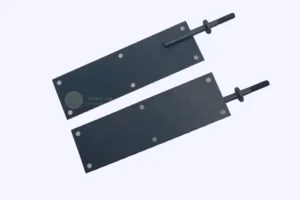

Which industries use ruthenium iridium coated titanium anode?
Ruthenium-iridium coated titanium anodes are commonly used in the following industries:
- Electroplating industry: To enhance the quality and efficiency of the electroplating process of metals.
- Chlor-alkali industry: Crucial in the electrolysis of brine to produce chlorine, hydrogen, and sodium hydroxide.
- Wastewater treatment: Facilitates the purification of wastewater containing refractory organic compounds through electrolytic oxidation.
- Hydrometallurgy: Such as the extraction and refining of metals like copper and zinc.
- Electronics industry: Applied in the electrolytic processes during the manufacturing of certain electronic components.
- Organic synthesis: Serves as an electrode to promote reactions in some organic chemical reactions.
- Marine engineering: For instance, in the anti-corrosion protection of ships.
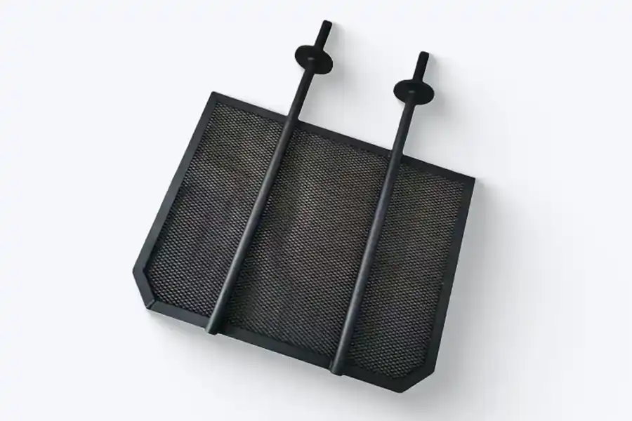
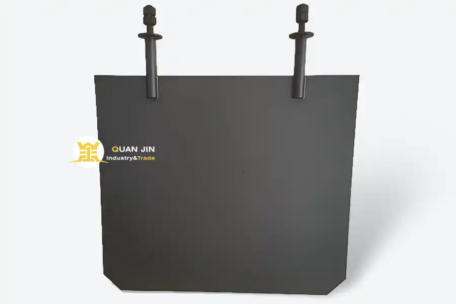
Ruthenium Iridium Coated Titanium Anode
Ru Ir titanium anodes is dimensionally stable anode (DSA), our ruthenium iridium coated titanium anode are insoluble titanium based anode with a ruthenium iridium oxide coating. Owing to their light weight, good temperature resistance and high mechanical strength, ruthenium-iridium coated electrodes are highly regarded as the most economic and practical choice for use in electrolyte containing a high content of chloride ions generally in the environment of hydrochloric acid and brine/seawater electrolysis.
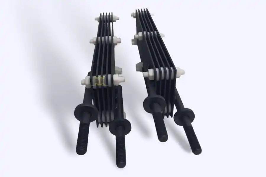
Ruthenium Iridium Coated Titanium Anode can be fabricated in forms such as perforated plate, sheet, mesh, rod, wire or basket.
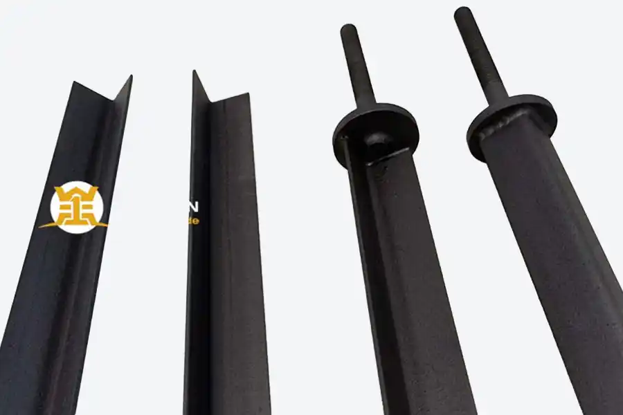

Our titanium anode with high selectivity, stable operational performance, remarkable energy efficiency and minimum plant downtime. These Ru-Ir titanium electrodes are widely used in chlor-alkali production, water treatment, water disinfection, primary metal refining, electroplating and many other electrochemical processes in which chlorine evolution represents the key anodic reaction.
What is the production process of ruthenium-iridium coated titanium anode?
The production process of ruthenium-iridium coated titanium anode typically includes the following steps:
- Pretreatment of titanium substrate: The titanium substrate is subjected to cleaning and degreasing to remove impurities and contaminants from the surface.
- Surface roughening: The surface of the titanium substrate is roughened through mechanical or chemical methods to increase the surface area and improve the adhesion of the coating.
- Preparation of coating solution: A solution containing ruthenium and iridium salts is prepared, along with other necessary additives.
- Coating application: The coating solution is applied to the titanium substrate by methods such as brushing, spraying, or electroplating.
- Thermal treatment: The coated substrate is heated to a specific temperature for a certain period to promote the formation of the desired oxide coating and improve its adhesion and electrochemical performance.
- Multiple coating cycles: To achieve the desired coating thickness and quality, the coating and thermal treatment steps may be repeated several times.
- Final inspection and quality control: The finished anode is inspected for coating uniformity, thickness, and electrochemical properties to ensure it meets the specified standards.
It should be noted that the specific production process may vary among different manufacturers, and they may have their own proprietary techniques and optimizations to produce high-quality ruthenium-iridium coated titanium anodes.
A ruthenium iridium coated titanium anode is a titanium current collector with a few micrometers of mixed ruthenium and iridium oxide fired onto it. The oxide is the electrode. The titanium is the package that holds it in place and carries current to it. Everything that decides whether the part lasts two years or six happens in the gap between those two sentences.
- Ratio sets the reaction. 80:20 is an industry default, not an optimum. It is chosen for clean brine and steady current, which is not every cell.
- Load sets the budget. 8–25 g/m² of noble metal. Past roughly 20 g/m² the extra grams buy less life than the first ones did.
- Current density sets the clock. Life follows charge per square meter, not the calendar. This is the variable most often set by accident.
- The interface sets the failure. Most dead anodes we examine died at the titanium surface, not in the brine.
01 — The part
The part is a stack, not a surface
Buyers tend to talk about “the coating” as if it were paint. It behaves more like a thin-film device with three layers, each doing a different job, and each able to end the service life on its own.
The bottom layer is the titanium substrate, usually Grade 1 or Grade 2 commercially pure titanium. It carries current from the busbar to the working face and holds the geometry that the cell was designed around. It is not a catalyst and it is not supposed to touch the electrolyte.
The middle layer is an oxide interlayer, a few tens of nanometers to a micron thick, that grows during firing where the precursor meets the metal. It is mostly TiO₂ with some iridium and ruthenium diffused into it. A good one is thin, dense and conductive. A bad one is thick, porous and insulating, and it will strangle the anode from underneath while the top coat still looks healthy.
The top layer is the catalytic oxide: RuO₂, IrO₂ and TiO₂ in a rutile solid solution, with a cracked, mud-like morphology that gives it somewhere to flex. This is the only layer the electrolyte should ever see.
That is why two anodes with identical mill certificates can diverge. The certificate describes what was applied. It says nothing about how well the first pass bonded, whether the furnace held its profile at pass fourteen, or whether the edge of the plate was still clean when it went into the coating booth. We have written about this separately in coating failure and maintenance; the short version is that the failure signature usually points at the interface.
From the coating shop
Anodes sent to us for autopsy rarely show a uniformly worn coating. They show a bright ring of bare titanium at a weld, a gray patch where the oxide lifted, or a white bloom of TiO₂ creeping out from under intact coating. The ruthenium did not evaporate. The bond failed, and the substrate oxidized.
02 — The surface
What is actually on the surface
The standard manufacturing route is thermal decomposition, and it has barely changed in fifty years. A precursor solution of ruthenium chloride, chloroiridic acid and a titanium source is dissolved in an alcohol or acid carrier, applied to a prepared titanium surface by brush, roller or spray, dried, and fired in air at roughly 400–550 °C. The salts oxidize; the chloride and the solvent leave. Then the part is cooled and the cycle repeats.
Ten to thirty passes is normal. Each one deposits a fraction of a micron, and each one is a chance for something to go wrong: a dusty surface, an uneven brush stroke, a furnace zone running cold.
What each oxide contributes
| Oxide | Job | Behavior worth knowing |
|---|---|---|
| RuO₂ | Chlorine evolution catalyst | Lowest chlorine overpotential of the common oxides, and metallic-type conductivity. It is also the least stable: at oxygen-evolution potentials it oxidizes to soluble, volatile RuO₄ and leaves. |
| IrO₂ | Stabilizer | Same tetragonal rutile lattice as RuO₂, so the two form a solid solution rather than separate islands. It raises the oxygen overpotential and slows ruthenium dissolution, at a cost in activity and price. |
| TiO₂ | Binder and diluent | Improves adhesion and thermal expansion match, and lowers cost. It also dilutes the active phase, so a high-titania coating is cheaper and less active. |
The rutile match is the reason this particular pair works. Iridium sits inside the ruthenium lattice and stabilizes the film as a whole, instead of protecting only its own grains. That is a different mechanism from Ir-Ta, where amorphous Ta₂O₅ acts as a surrounding matrix. If your cell evolves oxygen rather than chlorine, the iridium-tantalum coatingis the correct family, and no amount of ruthenium will fix it.
03 — Decision one
The Ru:Ir ratio is a trade, not a spec
Ratio is quoted as molar percent in the precursor, and most suppliers default to 80:20 because that is what the chlor-alkali industry settled on decades ago. It is a good default. It is not an optimum for every cell, and the difference in service life between a 80:20 and a 60:40 coating in the wrong application is not a rounding error.
Two things the datasheet will not tell you
The bath ratio is not always the film ratio. Ruthenium chloride is volatile in the firing window and some ruthenium leaves the surface as oxide vapor; iridium does not. A 80:20 precursor can fire to something closer to 85:15 at the surface. Ask for XRF or EDS on the finished coating rather than a copy of the formulation sheet. The number that matters is the one in the film.
Iridium is the expensive half. On a clean brine cell running steady current, the extra iridium in a 60:40 coat buys tolerance the cell will never use. On a seawater unit that trips on low flow twice a week, the same money buys years. The question is not which ratio is better. It is which failure mode you are actually exposed to.
Cost ranking reflects relative noble-metal content and iridium price, not absolute price. Iridium trades far above ruthenium and moves independently; check the ratio you are paying for, not just the loading.
Match the ratio to the worst hour the cell will see, not the average one.
04 — Decision two
Coating load sets the budget
Load is quoted in grams of noble metal per square meter. Production anodes usually run 8–25 g/m². Below 8 you are buying a short-life part; above 25 you are usually paying for thickness the coating cannot hold without cracking.
| Load (g/m²) | Typical duty | What you are buying |
|---|---|---|
| 8–10 | Clean water, low current density, short campaigns | Minimum viable coating. Fine for intermittent disinfection duty where replacement is cheap and easy. |
| 12–15 | Standard sodium hypochlorite generation | The mainstream specification. Two to four years in well-run cells at 1,000–1,500 A/m². |
| 18–22 | Seawater, cyclic duty, higher current density | Margin against scale, shutdowns and current excursions. Most of the benefit of going heavier. |
| 25+ | Heavy industrial, long campaigns, expensive downtime | Diminishing returns per gram, but the right call when a shutdown costs more than the anode. |
The relationship between load and life is close to linear, until it is not. Each pass adds a fired layer that shrinks as chloride converts to oxide, and the shrinkage puts the film in tension. Past a certain thickness the coating relieves that tension by cracking. Fine mud-crack patterns are normal and even useful: they let gas escape and give the film somewhere to move. Cracks that reach the metal are a different thing entirely. Once electrolyte touches titanium, the substrate oxidizes to insulating TiO₂, the local current has nowhere to go, and the effective area shrinks. The anode does not fail because the ruthenium ran out. It fails because a crack shorted the interface.
05 — Decision three
Current density is the clock
This is the variable with the most influence on service life and the least scrutiny during design. Anode life is set by the charge passed per unit of coated area. Calendar time is a poor proxy, because two cells with the same anode can run one shift a week or twenty-four hours a day.
The only life equation that matters
Q = j × t
Q = charge passed per unit area (Ah/m²) · j = current density (A/m²) · t = time (h)
expected life (h) =Q_capacity÷ j
Doubling current density does not exactly halve life — in practice it usually costs more than half, because higher current also means more oxygen co-evolution, more bubble coverage on the working face, and a hotter film. Treat the inverse relationship as the optimistic case, not the design case.
| Application | Current density (A/m²) | Why the window sits there |
|---|---|---|
| Sodium hypochlorite from dilute brine | 500–2,000 | Balances cell count against coating life; above 2,000 the chlorine selectivity and coating life both fall away. |
| Seawater electrochlorination | 600–1,200 | Hardness and scale set the ceiling more than electrochemistry does. |
| Chlor-alkali membrane cells | 3,000–6,000 | Driven hard for capital efficiency; coatings are formulated and loaded specifically for it. |
| Chloride-bearing wastewater | 200–1,000 | COD load and chloride concentration vary through the day; the low end protects the coating during upsets. |
| Cathodic protection, seawater | 100–500 | Current is set by the structure being protected, not by the anode. |
| Plating auxiliary anodes | 200–1,500 | Set by bath conductivity and the throwing power the part needs. |
Ranges describe common industrial practice for Ru-Ir coatings. They are not limits, and they move with temperature, chloride concentration and duty cycle. Confirm the envelope with the coating supplier for your specific electrolyte.
The edge is always working harder
Current does not distribute itself politely. It crowds at edges, at welds, and where the busbar meets the plate. Local current density on a sharp edge can run 1.5 to 2 times the nominal figure, which means that edge accumulates charge far faster than the middle of the plate. This is why so many autopsies begin with a bright line along a cut edge, and why deburring and edge radius are not cosmetic details.
Design current density is a drawing decision, and drawings tend to carry margin added twice. If the cell was sized at 1,500 A/m² and actually runs at 1,100, you either bought 36% more anode than you needed or you bought 36% more life. Both are acceptable. What is not acceptable is sizing at 2,000 A/m² and then discovering the rectifier can deliver 2,400 on a cold morning.
06 — Decision four
Substrate and geometry
Grade 1 or Grade 2 commercially pure titanium, per ASTM B265. Grade 1 carries less oxygen and iron and more ductility, which matters for expanded mesh and anything that gets bent. Grade 2 is stronger and machines better, which matters for plates, tubes and machined assemblies. Neither grade is a quality differentiator by itself. Plenty of short-lived anodes were made from perfectly certified Grade 1.
The differentiator is what happens to the surface before coating. Degrease, blast with angular alumina to Ra 3–5 µm, then etch in hot oxalic acid to strip the air-formed oxide and leave a hydride-rich, micro-pitted surface the first pass can key into. Skip the etch, or let the part sit long enough for the oxide to grow back, and the coating bonds to an oxide film instead of to metal. It will pass a visual check and a tape test. It will not survive a thousand hours.
| Form | Why it is chosen | What to watch |
|---|---|---|
| Plate | Uniform field, predictable area, easy to machine and replace. | Flatness and burrs. A bowed plate changes the gap, and the gap sets the local current density. |
| Expanded mesh | High geometric area per envelope, fast gas release, low IR drop through the electrode. | Projected versus developed area in the quote; sharp strand edges; coating bridging the openings. |
| Tube | Flow-through geometry for seawater, groundbeds and in-line cells. | Internal coating coverage and end seals. A tube coated only on the outside is half an anode. |
| Rod | Concentrated current for cathodic protection and plating racks. | Copper core sealing. A leak at the core joint ends the anode quickly and quietly. |
| Wire / ribbon | Deep well and tank protection, long runs at low current. | Bend radius. Coating cracks at tight bends, and the crack is where it fails. |
Welds are where a lot of good anodes go bad. Spatter, heat tint and smeared metal all sit under the coating and all fail early. Either weld before blasting and treat the weld like base metal, or keep the coating off the weld entirely and use a bolted connection. What you should not do is coat over an untouched weld and hope.
The same logic applies to the connection. A bolted joint with a passive oxide film between the busbar and the anode is a resistor, and it will heat. For plate and mesh anodes in hypochlorite generators, we machine the current-carrying tab bare and mask it during coating, then protect it during shipping.
07 — Decision five
The electrolyte decides more than the datasheet does
A coating is chosen for a reaction, but it lives in a chemistry. Six conditions in the water decide whether a Ru-Ir anode reaches its rated life, and most of them never appear on a purchase order.
| Condition | What it does | Threshold worth watching |
|---|---|---|
| Fluoride | Etches titanium through coating defects and lifts the film in sheets. The fastest killer on this list. | Keep below 2–5 ppm. Above that, a barrier layer or a different anode system. |
| Ammonia and amines | Oxidize preferentially at the anode, compete for active sites and form chloramines. | Any sustained presence needs bench testing before you commit to a coating. |
| Calcium and magnesium | Scale the working face, create crevices and force local acidification under the deposit. | Soften the feed, or put acid cleaning on a schedule instead of on a hunch. |
| Hypochlorite in the cell | Reduced back to chloride at the cathode; oxidized onward to chlorate at the anode. | Hold cell outlet around 8–12 g/L available chlorine. Higher concentration buys you nothing and costs current efficiency. |
| Temperature | Accelerates RuO₂ dissolution and coating creep, and lowers chlorine solubility. | Keep the film below 60–65 °C. Above that, life falls faster than temperature alone would predict. |
| pH | Below 1.5 attacks the oxide; above 12 attacks the titanium at any coating defect. | Control at the cell, not downstream in the storage tank. |
Hardness is the one that gets ignored, because it does not fail the anode — it just makes the cell expensive. Scale is both an insulator and a crevice former. Voltage climbs, the operator turns up the rectifier, local current density rises, and the coating dies of a problem that started in the water softener.
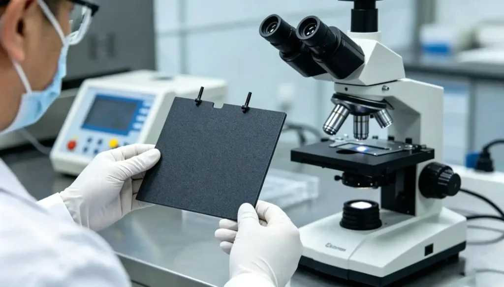
Why a 5 kA cell does not make 6.6 kg of chlorine an hour
Faraday’s law gives the ceiling. One ampere for one hour liberates 1.323 g of chlorine, so a 5,000 A cell tops out at 6.6 kg/h. Real cells deliver less, because an unseparated hypochlorite cell is a small war between reactions: chlorine formed at the anode is partly reduced back to chloride at the cathode and partly oxidized further to chlorate. Both losses grow as hypochlorite concentration and temperature rise.
That is why current efficiency on the datasheet deserves as much attention as coating load. A cell running at 80% efficiency needs 25% more charge for the same tonnage of chlorine — and that charge comes out of the coating’s budget. If you are comparing anode offers, compare them at the efficiency the cell will actually hold, not the one on the brochure.
Where the chloride stream is dilute or the water is hard, the answer is often a different geometry rather than a different coating. Our notes on seawater electrochlorination and marine electrochlorination cover the plumbing side of that trade-off.
08 — The arithmetic
Working out what you are actually buying
Anode life is not a property of the coating alone. It is a property of the coating, the area it is spread over, and the current you push through it. That makes it calculable, at least to the accuracy of the capacity figure you start from.
Swipe the diagram →
Here is the same thing with numbers a project engineer can use. Take a 5,000 A hypochlorite cell running 8,000 hours a year, designed at 1,500 A/m², with a supplier who has field data showing 30,000 kAh/m² at those conditions.
Worked example
Anode areaA = 5,000 ÷ 1,500 = 3.33 m²
Charge per m² per year1,500 × 8,000 = 12,000 kAh/m²
Expected life30,000 ÷ 12,000 =2.5 years
Now derate the same cell to 1,000 A/m². The anode grows to 5 m², the annual charge per square meter falls to 8,000 kAh/m², and the expected life rises to 3.75 years. You spend 50% more on anode area and get 50% more service. Whether that is a good trade depends on the cost of a shutdown, not on the price of titanium.
That last point is worth stating plainly, because anode procurement is usually run as a price comparison and the number that decides the outcome is downtime. A set of anodes that costs 30% more and lasts 50% longer is the cheaper option in almost any plant where the cell is on a production line. It is the more expensive option in a swimming pool plant where replacement is a two-hour job.
Where the capacity figure comes from — and where it does not
Accelerated life testing is the industry’s standard quality check. A coupon is run in 1 M sulfuric acid at 20,000 A/m², typically following a protocol such as HG/T 2471, and the time to a defined voltage rise is recorded. It is excellent for ranking two coatings against each other and for catching a bad batch.
It is not a life predictor. The test drives oxygen evolution in acid; your chlorinator drives chlorine evolution in brine. Different reaction, different dissolution mechanism, unknown acceleration factor. A coating that wins the acid test can lose in seawater. Use ALT to compare suppliers, and use field data — same electrolyte, same current density, same water — to estimate life.
Size it yourself
Move the sliders · results update live- Anode area
- 3.33m²
- Chlorine output
- 127kg/day
- Specific energy
- 3.78kWh/kg
- Expected life
- 2.5yr
Area, output and energy follow from Faraday’s law and the inputs above. Life depends entirely on the coating capacity figure, which must come from your supplier’s field data at your current density and water chemistry. Treat the output as a planning estimate, not a warranty.
09 — Procurement
What to put in the RFQ
A coating supplier cannot specify what you do not tell them. Most of the quotes that go wrong for the buyer start with a drawing and a current rating, and no water analysis. The list below is the minimum for a quote that means something.
- Full electrolyte analysis: Na⁺, Cl⁻, hardness, sulfate, fluoride, ammonia, TOC
- pH at the cell, not at the storage tank
- Temperature at the anode, minimum and maximum
- Current per anode and total rectifier rating
- Design current density, plus the maximum the rectifier can actually deliver
- Duty: continuous, intermittent or cyclic, and hours per year
- Shutdown and polarity-reversal behavior
- Geometry envelope, connection type and busbar material
- Cleaning method and frequency: acid wash, mechanical, or none
- Target service life and the cost of a day of downtime
- Documentation required for acceptance
- Whether recoating of the existing substrate is acceptable
Documentation worth paying for
| Document | What it proves |
|---|---|
| Mill certificate | The titanium is what the drawing says it is, heat by heat. |
| Coating load record | Weight difference per part, before and after coating, on a calibrated balance. |
| XRF or EDS report | The Ru:Ir ratio in the fired film, not in the precursor bath. |
| Adhesion test | Tape or bend test results, with the method stated. |
| Accelerated life test | Batch ranking, with electrolyte, current density, temperature and failure criterion written down. |
| Dimensional report | Flatness, hole pattern, tab position, connection thread. |
10 — Diagnosis
How they fail, and what each failure tells you
Anode failures are legible if you look at the right surface. The pattern on the plate usually names the cause, and the cause is usually upstream of the coating line.
| What you see | What it means | What to change |
|---|---|---|
| Voltage climbs steadily over 12–24 months, coating thin but intact | Normal depletion. The coating is being consumed at the expected rate. | Accept it, or raise load and lower current density on the next order. |
| Voltage jumps within the first 500–1,000 hours | Substrate passivation from a poor etch or a porous first pass. | Audit surface preparation. Ask for a cross-section, not a new anode. |
| Bright bare ring at a weld or cut edge | Coating burned back, masked, or never applied at fabrication. | Change edge prep and masking sequence; radius the edge. |
| Gray or white film, slow voltage creep in hard water | Scale. Insulating layer plus crevice formation. | Soften the feed, schedule acid cleaning, check the polarity cycle. |
| Coating blisters and lifts in sheets | Contamination before firing: oil, fingerprints, dust, spent blast media. | Handling discipline between etch and first pass. |
| Titanium brittle, cracked, gray-hydrided | Cathodic excursion or polarity reversal without protection. | Blocking diode, and keep the anode under cathodic protection when de-energized. |
| Pitting concentrated under a gasket | Crevice corrosion. Stagnant electrolyte in a shielded gap. | Redesign the seal, add flush, avoid coating under the gasket. |
| Rapid loss in a fluoride-bearing stream | Chemical attack on the substrate through coating defects. | Barrier layer, or a different anode chemistry entirely. |
One pattern is worth calling out because it is misread so often: an anode that fails at the edge while the center is still black and healthy is not a coating quality problem. It is a current distribution problem, and a replacement anode will fail in the same place unless the geometry changes.
Questions we get asked before an order
Can I run a Ru-Ir anode in dilute sulfuric acid?
Only while chlorine evolution stays dominant. At oxygen-evolution potentials, RuO₂ oxidizes to soluble RuO₄ and leaves the surface, and the loss can be fast. If the stream has enough chloride to keep chlorine as the main reaction, a Ru-Ir coating can work. If it does not, specify Ir-Ta, which is built for oxygen evolution in acid. The
titanium anode guide walks through the CER versus OER logic in more detail.
How long will a Ru-Ir coated anode actually last?
Two to six years is the honest range for hypochlorite and seawater service, and that range is wide because the inputs vary. The useful answer is a charge number: give us current density, hours per year, temperature and a water analysis, and we will come back with kAh/m² and a life estimate instead of a slogan.
Why does the cell voltage rise every summer?
Warmer water accelerates RuO₂ dissolution and shifts the hypochlorite equilibrium toward chlorate, so current efficiency falls and the coating works harder for the same output. If the cell is temperature-limited, either derate the current in the hot months or add anode area. Acid cleaning on a calendar schedule also helps, because scale growth is faster in warm hard water.
What is the difference between coated area and active area?
Coated area includes the whole coated surface, sometimes including tabs and margins that never face a cathode. Active area is the part that actually carries the reaction. Two quotes compared on different definitions can differ by 20% before anyone talks about price. Normalize to active area, and state which one you are using.
Send the water analysis, not just the drawing.
Tell us the electrolyte, the current density and the hours per year. We will come back with a coating system, a load, and a life estimate with the assumptions written down.